Ch1 - Basic Definitions
[Definition] An electric circuit is an interconnection of electrical elements
[Definition] Current is the ROC (Rate Of Change) of charge flow past a given point in given direction
Direction of current is conventionally taken as the direction of positive charge movement
Direct Current - Current flows in only one direction
Alternating Current - Current that changes direction with respect to time
[Definition] Voltage is the energy required to move 1C of charge from a reference point(-) to another point(+)
The force that does the work is called emf(Electricmotive Force). Which is known as voltage? or potential difference (这里是不是讲错了)
dc voltage - Constant voltage, noted by
ac voltage - Time-varying voltage, noted by
The term signal is used for an electric quantity (current, voltage or magnetic wave) when it is used for conveying information
Current pass through an element, Voltage is across an element
[Definition] Power is the time rate of expending/absorbing energy, measured in watts(W)
Passive Sign convention:
所有这些都是标量,但却有方向
计算时先假设一个方向,计算后如果是negative证明跟假设相反
对于电压,
当计算出来的p>0(电流从高电压到低电压),元器件在耗能(dissipate power),反之,元件在供能(supply power)
答题的时候注意给的power是supply还是dissipate
根据能量守恒定律
Total power supplied = Total power absorbed
[Definition] Energy is the capacity to do work, measured in joules(J)
有的题计算耗能的时候,需要复杂的积分,要牢记各种积分技巧
Circuit Elements
Active/Passive elements: Determined by the capability of generating energy.
An ideal independent source is an active element that provides a specificed voltage/current completely independent of other circuit elements
圆圈中间有+-的是电压源,可以是常量,也可以是time varying
如果是两条线的电压源,则只能是常量
圆圈中间是个箭头的是电流源
An ideal dependent/controlled source is an active element in which the source quantity is controlled by another voltage/current
Dependent source的图标是菱形
共有4中dependent source: Voltage/Current controlled voltage/current source (XCXS, X是V或者C,代表Voltage/Current)
Dependent sources are useful in modeling elements
Ideal source could in theory supply an infinite amount of energy
Ch2 - Basic Laws
Resistance of Conductors
[Definition] Resistor is the circuit element used to model the current-resisting behavior
Ohm's Law
The voltage v across a resistor is directly proportional to the current i flowing through the resistor
Ohm defined the constant of proportionality for a resistor to be the resistance, R.
[Definition] resistance R of an element denotes its ability to resist the flow of electric current, measured in ohms(
When applying Ohm's law, the direction of the current and polarity of voltage must confirm with passive sign convention(current flows from higher potential to lower potential)
[Definition] short circuit is a circuit element with resistance approaching 0
[Definition] open circuit is a circuit element with resistance approaching infinity
Resistors can be constant or variable. Constant resistors have a fixed resistance, variable resistors' resistance can be changed.
A resistor that obeys Ohm's law is known as a linear resistor
[Definition] Conductance is the ability of an element to conduct electric current, measured in mhos(
Nodes, Branches and Loops
[Definiton] A branch represents **a single element
[Defintion] A node is the point of connection between two or more branches
注意,串联的两个元器件中间也有一个node
[Definition] A loop is any closed path in a circuit
A loop is said to be independent if it contains at leas one branch which is not part of any other independent loop.
b - branch number(number of elements), l - number of independent loops, n - number of nodes
[Definition] 2 or more elements are in series if they exclusively share a single node, so they carry the same current
[Definition] 2 or more elements are in parallel if they are connected to the same two nodes, consequently have the same voltage across them
Kirchhoff's Laws
Kirchhoff's current law(KCL) - The algebrac sum of currents entering a node(or a closed boundary) is 0
N - Number of branches connected to the node/closed boundary,
Current entering = Current leaving
KCL is based on the conservation of electric charge
Kirchhoff's voltage law(KVL) - The algebrac sum of all voltages around a closed path(or loop) is 0
M - Number of voltages(branches) in the loop,
Voltage rise = Voltage drop
KVL is based on the conservation of energy
, where i is the same across all elements
Voltage & Current Dividers
Series Resistors - Voltage Division
i 相同
Parallel Resistors - Current Division
v 相同
对于两个Resistor
永远小于所有并联起来电阻中最小的那个 对于N个相同的Resistor
Current Divider对于两个电阻
Wye-Delta Transformations
用Nodal Analysis可比这个快多了,看个乐子即可
转换的原则是3个节点间两两结合的3种方式,转化前和转化后的阻值都不变
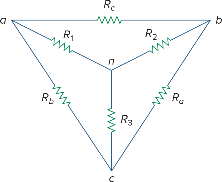
Delta->Wye (∆/∏ -> Y/T)
Wye->Delta(Y/T -> ∆/∏)
关于电压表原理问题
机械型电压表实际上是由电流表改装而来,等效于一个大电阻+电流表,所以实际测得是电流
电压表的示数是
*内阻
Ch3 - Nodal Analysis and Mesh Analysis
Nodal Analysis
Select the reference node (或叫做datum node),设其为0V,作为ground,并把其他Node写成未知数v1, v2, ..., vn
对每个nonreference node用KCL列出电流式 (
算矩阵
参考节点的选择 - 3种地及其符号
机壳地 - 连接到机壳的符号
地球地 - 箭头(Common ground)或者GND的三道杠
Ground - 三道杠
计算矩阵时,如果手算的话,使用Cramer's rule (当然,rref也是不错的选择)
Nodal Analysis with Voltage source
对于电压源,我们不清楚流过它的电流,只能使用特殊手段计算
Case1 - 当电压源跟reference node(ground)连在一起时,把电压源连接的non-reference node设置为相应的电压
Case2 - Supernode
[Definition] A supernode is formed by enclosing a (dependent or independent) voltage source connected between two nonreference nodes and any elements connected in parallel with it
其实跟找普通node一样的,如果你发现一个元器件的两端连接在了同一个node上,那这个元件就被短路了
在这里,相当于把电压源两端的non reference node合二为一,同时去掉被短路的元器件
A supernode has no voltage on its own, 你不能给supernode设一个电压,然后计算,必须求出电流
现在,把supernode作为一个node对待,然后对每个node使用KCL,对于Supernode,设与其相连的线路上电流为i1, i2, ..., in
然后,找电压源所在的loop,对每个independent loop做KVL
这时你应该有足够的方程来计算所有未知数了
Shortcut for Nodal Analysis with only Independent Current Sources and Linear Resistors
当电路中只有电流源和线性电阻时,可以快速写出矩阵
Mesh Analysis
Mesh analysis is also known as loop analysis or the mesh-current method
[Definition] A mesh is a loop that does not contain any other loops within it
The current through mesh is known as mesh current
标记电路中所有mesh,并设mesh current为i1, i2, ..., in (电流的方向通常是顺时针,当然,逆时针也能算出来)
对每个Mesh用KVL
算矩阵
为了防止混淆,通常将设的mesh current用i表示,而branch current用大写I表示
Mesh Analysis with Current Source
[Definition] A supermesh results when two meshes have a (dependent or independent) current source in common
当合并后的supermesh还和其它mesh共用时,继续合并
A supermesh has no current on its own - Supermesh中,不同部分的电流并不同,不能当作一个整体计算
对于supermesh,使用KVL时,相应mesh的element要用相应的电流
最后,在被合并成supermesh的mesh的共同node上用KCL
Shortcut for Mesh Analysis with only Independent Voltage Source and Linear Resistors
当电路中只有电压源和线性电阻时,可以快速写出矩阵
Nodal Analysis vs. Mesh Analysis
根据分析方法本身的特性:
Mesh analysis can only be applied to planar circuits - circuits that can be drown in a plane with no branches crossing one another (otherwise it's nonplanar)
Mesh analysis cannot analyze op amp circuit
Nodal analysis is more general, and more amenable to solve by computer
Mesh analysis is the only method to use in analyzing transistor cicuits
根据电路特征:
如果node比mesh少,那nodal analysis合适,反之则mesh
实际做题时候,也可以根据电源的特征,如果全是电流源,nodal比较合适,反之mesh
根据要求的值:
求电压用node,电流用mesh
DC Transistors
教材的application部分讲述了一些三极管Transistor的原理,不过感觉讲的不是很明白
Transistors are active, three-terminal devices
Two basic types of transistors:
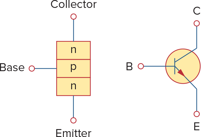
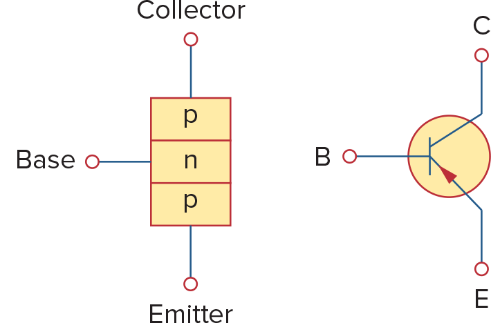
bipolar junction transistors(BJTs) - 包括pnp和npn两种
Field-effect transistors(FETs)
 |  |
|---|
1对于npn transistor:
根据电流方向:
在最外面画一圈,在这个圈上做KVL:
BJT有三种模式 - active, cutoff, saturation
当在active模式下,通常
Emitter极电子有
还有一个特征值
结合上面所有式子,可以得出
三极管的
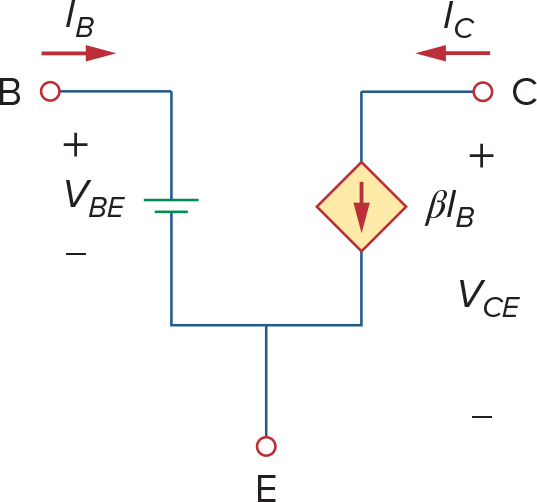
因此,在active模式下,三极管可以作为CCCS使用(Current Controlled Current Source),经常被用在放大器
所以也可以用如下电路来model active 模式下的transistor,这样就可以对电路做Mesh/Nodal Analysis了
Ch4 - Circuit Theorems
Linearity
[Definition] A linear circuit is one whose output is linearly related to its input
记得线代里面的linear relationship
应用 - 单个independent source的电路中,每个元器件的电流与电压跟电源的输出呈线性关系
Superposition
Superpostion principle: The voltage across/current through an element in a linear circuit is the algebrac sum of the voltages across/current through that element due to each independent source acting alone
Superposition principle用于分析多个independent source的电路
每次考虑一个independent source,将其它所有independent souce全都turn off
turn off, killed, made inactive, deadened, set equal to 0 这些词都表示忽略掉一个source
对于电流源,让它变成0A(断路),对于电压源,让它变成0V(短路)
注意跟电压表和电流表截然相反
通过一个被动元件的电流与电压(所有线性值)等于所有之考虑单个source时相对应的值相加
所以power不能直接通过superposition计算,因为
, 要求只能用superposition求i,然后算出p,不能直接superpostion p
Source Transformation
类似Wye-Delta Transformation, Source Transformation用于简化电路,让其易于分析
这几种transformation的基本原理都是equvilance等效
equivalent circuit - two circuit that has identical v-i characteristics
电压源串联电阻 <-> 电流源并联电阻
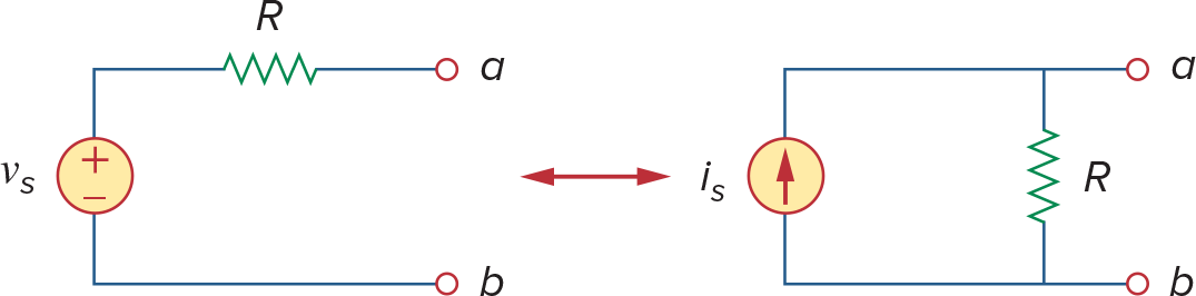
当电源关闭时,电压源短路,a - b电阻为R,电流源断路,a - b电阻为R
电源开启时,想象a,b短路,此时
不光是ab短路的情况,任何情况的可以证明
同理,dependent source也可以用相同方式进行转换
转换不影响电路的其它部分
Source Transformation无法用于ideal source,ideal voltage source R = 0, ideal current source R = ∞
不过对于现实中的source,基本都可以转换
使用Source Transformation解题的时候不要去动那些dependent source依赖的电阻, leave them intact
Source transformation之后原来被测点的值不再具有代表性,要么不transfer他们,要么通过transfer算出某一个电阻的电压之后恢复原来的电路计算(比如进行thevenin-norton transform时)
Thevenin's Theorem
A linear two-terminal circuit can be replaced by an equivlent circuit consisting of a voltage at the terminals and
就是一个电压源串一个电阻的组合,电压源的电压是
, 串联的电阻是
is the open circuit voltage across the terminals
is the input resistance at the terminals when the independent sources are turned off 如果电路中只有independent source, 那么可以直接通过turn off所有source,并且串并联电阻找到等效电阻
注意turn off voltage source会变成导线(0V),而turn off current source会是断线(0A)
可以直接通过电路分析找到
在terminal接一个电流源,电流源两端电压
在terminal接一个电压原,求流过电压原电流
给terminal短路,求短路电流,
如果求出来
为负,说明电路在supplying power
Norton's Theorem
A linear two-terminal circuit can be replaced by an equivalent circuit consisting of a current source
一个电流源并联电阻的组合
is the shortcircuit current through the terminals
由Source Transformation,我们可以知道
因此
可以看到,Thevenin和Norton实际上就是一个Source Transformation的关系,所以Source Transformation 也常常被叫做Thevenin-Norton Transformation
因此,
*Thevenin 和 Norton定理的证明
可以使用Superposition Principal证明这两个定理
假如对于一个有i1, i2两个电流源, v1,v2两个电压源的电路中(都是independent)
那么terminal voltage
其中i是流过的电流,A是每个电源对最终电压的weight
那么
而剩下那些则是一个固定值
同理也可以证明Norton定理
Maximum Power Transfer
对于任何线性电路,转化成Thevenin定理的形式后,能够输出的功率是
其中
那么电源的功率是有最大值的,当
当
时,功率还是需要用上面的功率公式求
Applications - Source Modeling
Practical voltage and current sources aren't ideal, due to internal resistances or source resistances (
Voltage source - internal resistances -
当
或 时,输出电压稳定 当没有load时,
, so may be regarded as unloaded source voltage The connection of the load causes the terminal voltage to drop in magnitude, known as the loading effect
Current source - source resistances -
当
或 时,输出电流稳定
测量电源内阻: 连接一个可调电阻作为load,调节电阻直到电阻的电压/电流 = 电源电压/电流 的一半,电源内阻跟可调电阻阻值相同
Applications - Resistance Measurement
Wheatstone bridge - 用于测量中等阻值(1
测量小阻值的是milliohmmeter, 测量大阻值的叫Megger tester
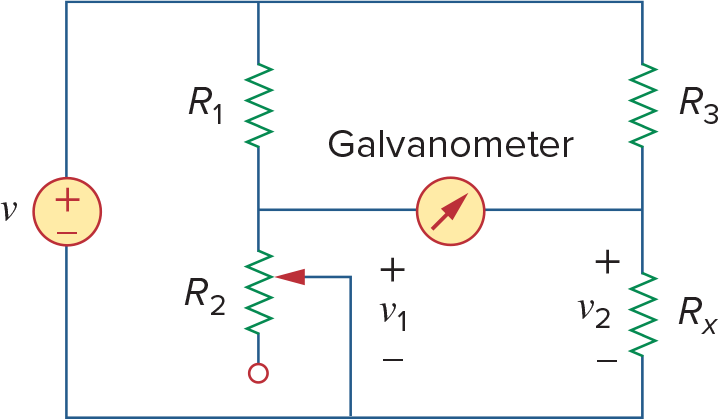
Galvanometer - d'Arsonval movement - 理解为灵敏电流计, operate in microamp range
When v1 = v2, the bridge is balanced,此时
When bridge is unbalanced,
Ch5 - Operational Amplifiers
这章教材讲的不太符合正常人的学习思路,适合复习
推荐用下面的资料了解
https://www.youtube.com/watch?v=_o4ScgRZtNI https://www.allaboutcircuits.com/textbook/semiconductors/chpt-8/introduction-operational-amplifiers/
https://ultimateelectronicsbook.com/ideal-op-amp/
尤其是positive和negative feedback的部分,理解了就ok了
Op Amp基础介绍
An op amp is an active circuit element designed to perform mathematical operations of +,-,*,/,differentation and integration.
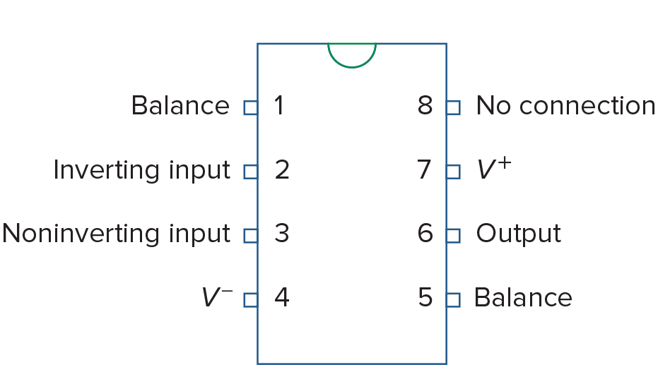
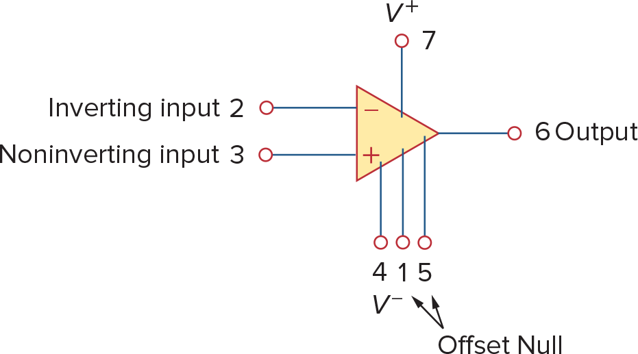
741 General Purpose op amp (Fairchild Semiconductor) 针脚定义
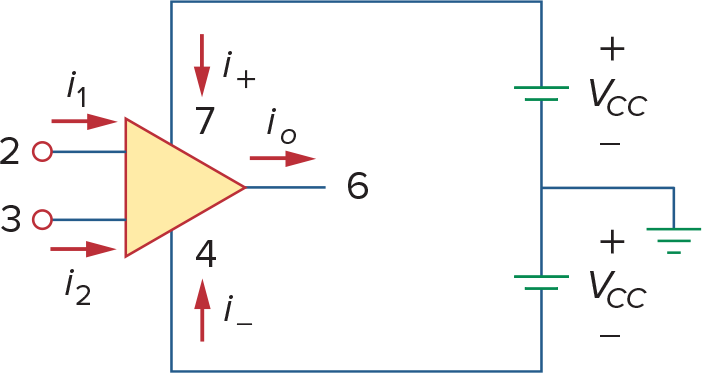
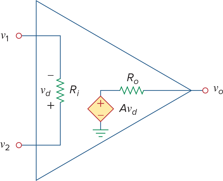
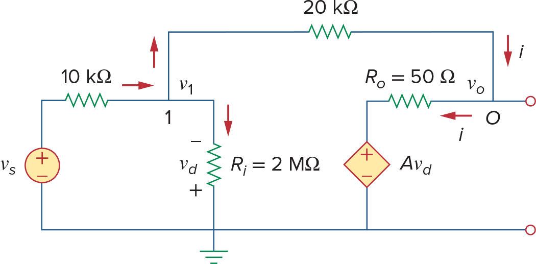
左边是op amp的供电图,右边是op amp的等效电路,注意两点:
op amp输出最大电压不超过供电电压
op amp会输出电流
单个op amp相当于比较器,当+极信号大于-极时,输出最大电压Vd,反之-Vd
A is called open-loop voltage gain,一般都非常大,有时会用dB表示,
| Parameter | Typical range Ideal values |
|---|---|
| 5~24V |
Op Amp的3种工作模式
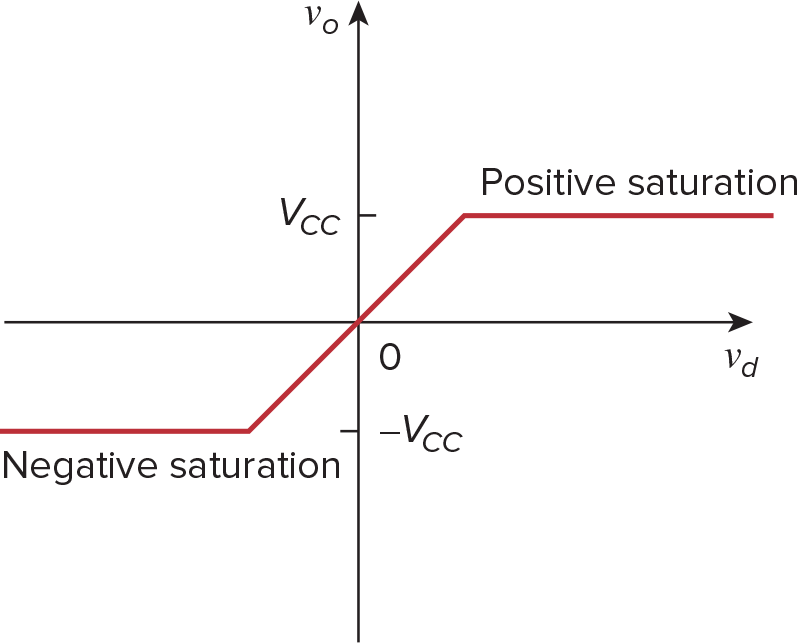
Positive Saturation
Linear Region
Negative Saturation
Feedback Loop
实际使用中,为了能够用op amp进行运算,会连接feedback loop Positive Feedback(把输出连接到Non-inverting input)会把电压拉到极值(使用positive feedback的比较器输出更稳定一些) Negative Feedback(把输出连接到inverting input)会让电压保持在一个平衡点,本章用的多是negative feedback
当存在Feedback Loop时,the ratio of output voltage and input voltage is called the closed-loop gain
这个closed-loop gain与open-loop gain基本无关(对于理想op amp则是完全无关),closed-loop gain由op amp的外围元器件决定
Non-ideal Op Amp的计算
将Op Amp看成Voltage Dependent Voltage Source
Ideal Op Amp
Op Amp is ideal if it has the following characteristics
Infinite open-loop gain -
Infinite input resistance -
Zero output Resistance -
Virtual Short虚短
这篇文章讲得还不错
虚短的性质只在含有negative feedback的电路中存在
比如现在Op Amp中有一个Negative Feedback,那么如果-极电压小于+极电压,输出电压就会增大(
如果能理解op amp这个平衡的过程对之后分析电路很有帮助
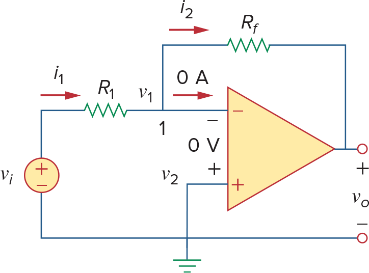
因此电流也满足
教材上是直接用电流=0推出来的电压相同,不过两种方式都要求op amp电路含有feedback loop并且在Linear Mode下工作
因此我们称op amp的两个input为"虚短"Virtual Short
各种常见Amplifier
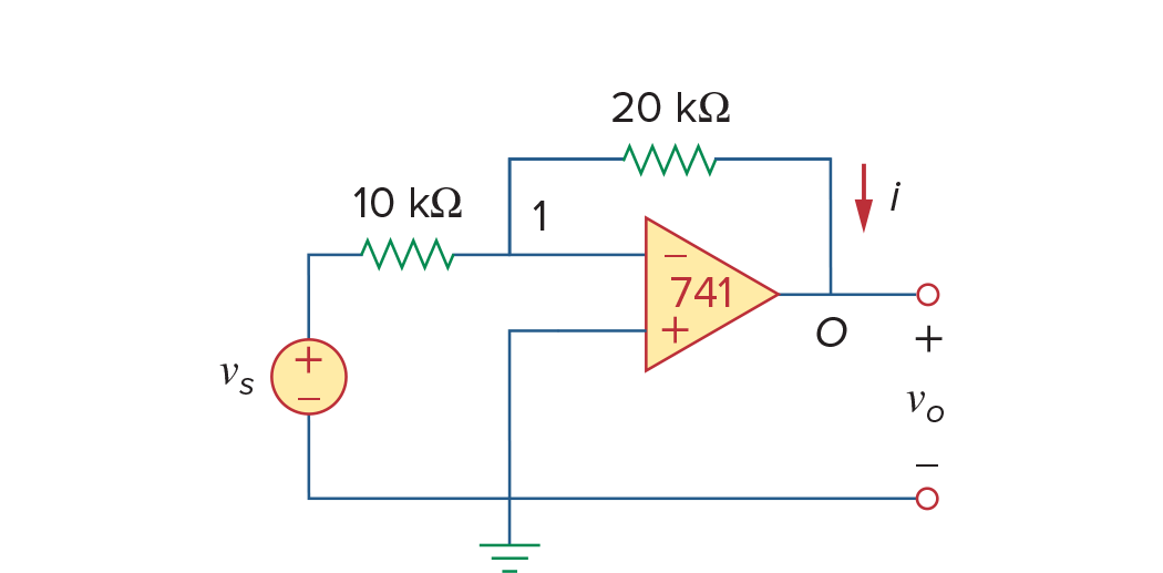
Inverting Amplifier
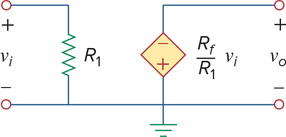
可以看到等效电路就是个VCVS
Transresistance Amplifiers (Current -> Voltage converters)
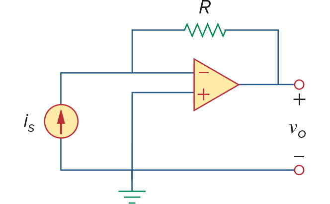
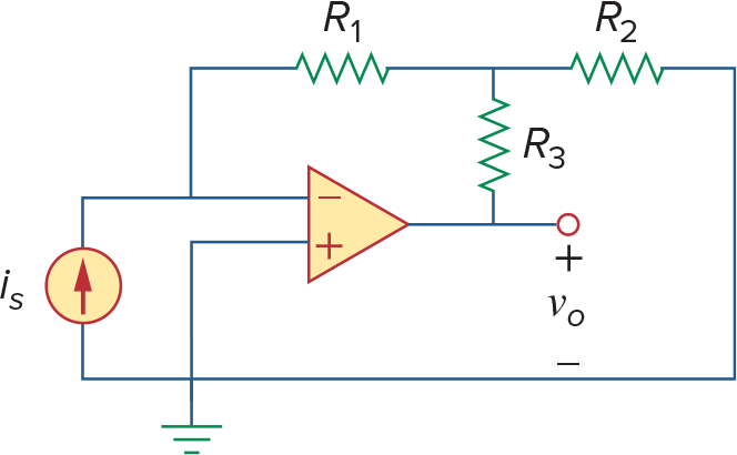
左边电路:
注意分析第二个电路时候记得Amplifier的输出是会有输出电流的,且不受限于KCL
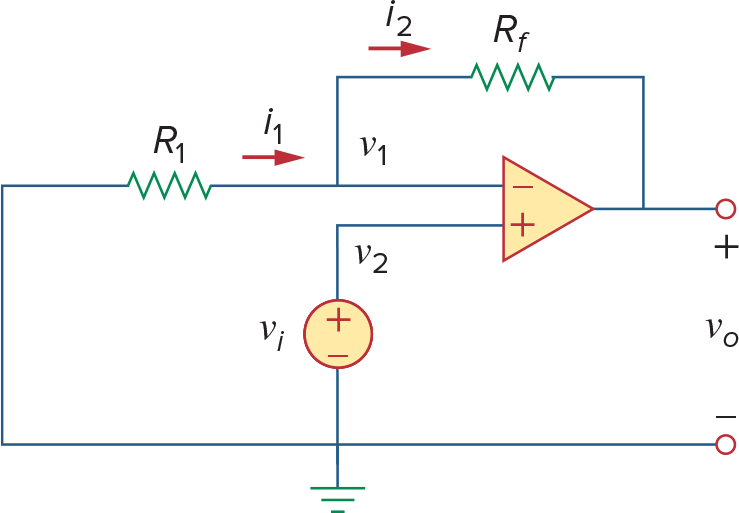
Noninverting Amplifier
特殊情况:Voltage Follower(unity gain amplifier), Rf = 0
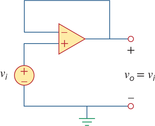
此时
,可以理解成信号延长器,因为之前也看到op amp可以当作VCVS,所以这里能够隔离两个电路,同时提供更充足的电流
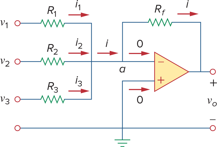
Summing Amplifier(Summer)
Difference Amplifier
这个电路其实严格来说不是Difference Amplifier
Difference Amplifier必须消除共模信号(当
时输出0) 因此必须满足
那么此时
这才是difference amplifier
当一个diffirence amplifier又同时满足
, 时
此时叫做subtractor
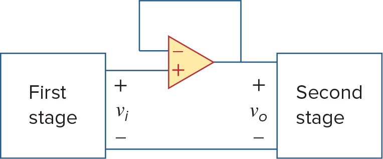
Cascaded Op Amp Circuits
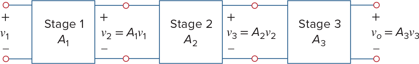
Two circuits are cascaded when they are connected in tandem, one behind another in a single file.
When op amps are cascaded, each circuit in the string is called a stage
Op amp在cascaded的时候不会改变它自身的Closed Loop gain,因此我们能够很方便的算出来多个Op Amps串连之后的总Closed Loop Gain (这个性质是由于Ideal Op Amp的性质得到的)
也需要注意每个阶段的Op Amp是否Saturate,如果由Saturate的情况,则结果是分段函数
所以如果能牢记上面几种Op Amp的样子,在分析多个Op Amp的时候就能很方便的找到关系
Applications
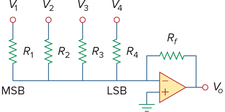
Digital-to-Analog Converter(DAC)
利用Summer,给不同的bit不同的权重
Instrumentation Amplifier
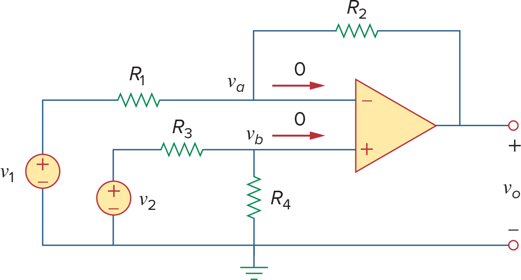
先来看这个Difference Amplifier,不过中间多了个电阻R4
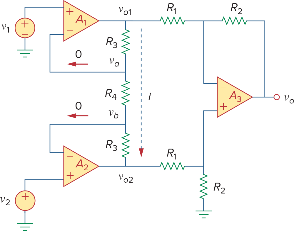
分析这个电路比这个结论重要的多,后半段是一个difference amplifier,前半段可以通过虚短的性质算出
一个Instrumentation Amplifier就是用的上面的电路,不过将R4变成可调电阻,这样就可以调整差模信号的放大倍数
Instrumentation Amplifier的3大性质
Voltage gain只由
2个Input Impedance都很高,且与
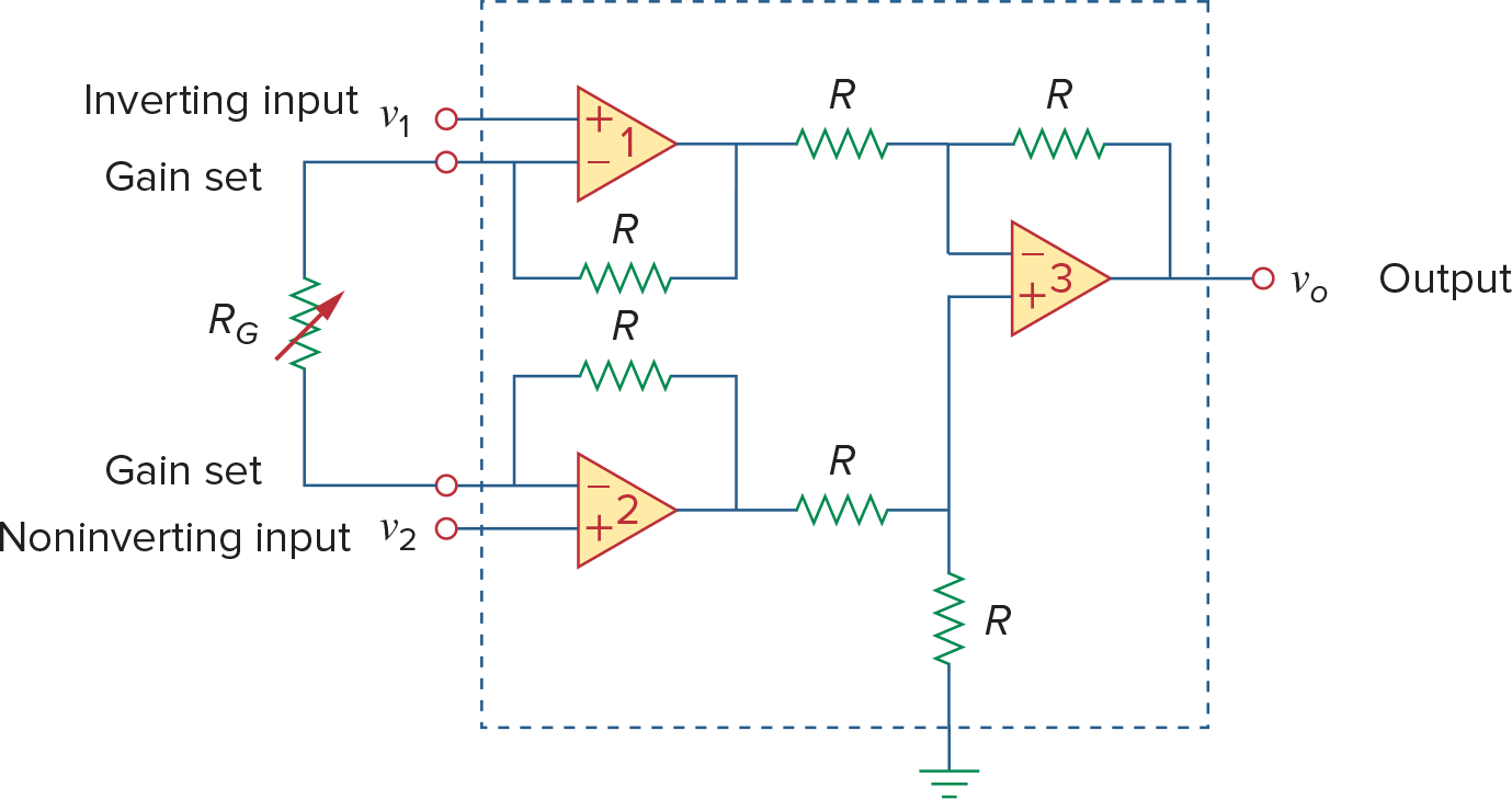
IA 的变种[难]
看会这两个运放可以通关了
这两种电路也可以实现IA的功能
这个电路的分析从左边入手,先把
这样对
下面减去上面得到
可以看到后半段是difference amplifier,因此
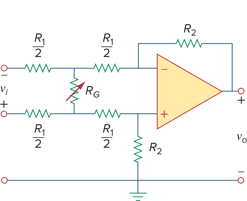
现将左边的
首先对op amp的两个input做KCL
所以到这里前半段相当于difference amplifier
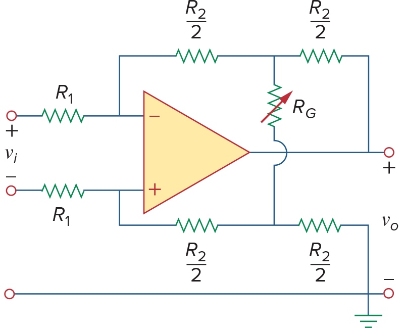
然后对
这次上下相加得到
注意这里它把
设定的是上面是+,下面是-,所以电压反了过来